The DISC Drill
Here's some pictures of the DISC drill at WAIS.
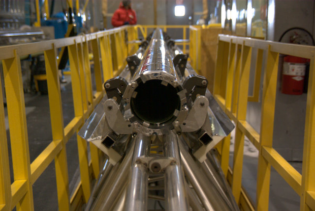
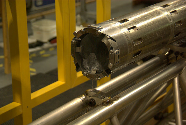
Here's the cutter head of the drill. The blades are at about the
2:00, 5:00,
8:00, and 11:00 positions. The core dogs, which are one way cams
that grab
the ice core and break it off for transport to the surface are at 1:00,
4:00,
7:00 and 10:00 positions.
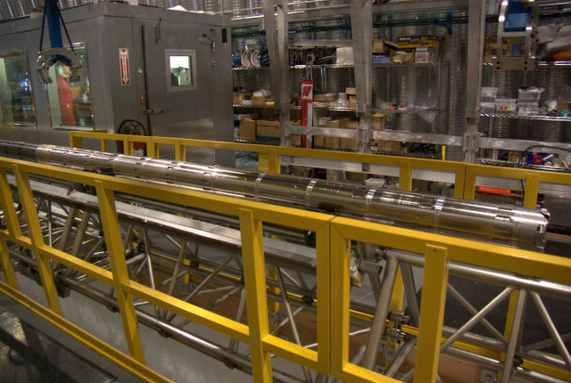
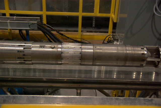
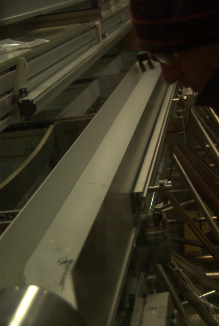
New for this year, is the thin kerf cutter barrel. It goes from
the cutter head
on the right to the brass band on the left, below the crane hook and
between
the two large windows on the control room. The thin kerf cutter
barrel
produces fewer ice chips, allowing longer ice cores to be cut before the
screen barrel is full.
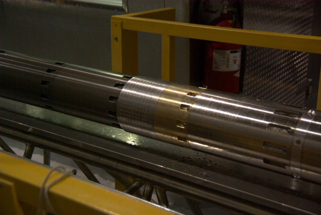
Here's the joint which separates the cutter barrel on the right from the
darker screen barrel on the left.
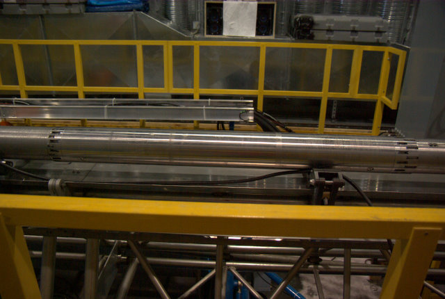
The screen barrel is the longest portion of the drill, and is not fully
pictured
in these shots. However, you get the idea; once you've seen one
screen
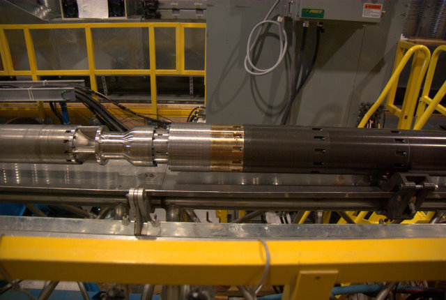
barrel portion, you've seen them all. This brass joint is the top
of the screen
barrel on the right, and the pump on the left. The pump
circulates the drilling
fluid with the ice chips from the cutter, over the ice core being cut,
up into
the cutter barrel screen barrels. Every time the drill
comes
to the surface with
another ice core, both the cutter barrel and screen barrel sections are
detached.
The cutter barrel then has the ice core removed. The screen
barrel section is
exchanged with another clean screen barrel section. The barrels
are then
reconnected and the drill is sent down again. The screen barrel
full of ice chips
is then cleaned.
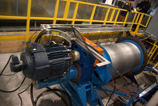
This is the motor section. It starts at the top end of the pump,
which is the
open area on the right. and ends with the blue screws on the
left. There are
two motors in this section. One for the cutter, and the other for
the pump.
The center ribbed portion is a heat sink to transfer heat away from the
motors.
To the left is the instrument section.
This is the instrument section. Not much to look at from the
outside, it
holds the brains and electronics of the drill. It is a sealed,
surface pressure,
container. It holds two computers, fiber optic modules, numerous
power supplies,
sensor electronics, power modules to drive the motors, a navigation
module, lots
of wires, and a gerbil inside to keep it all running.

The top section is the anti-torque section. The four springs keep
the top of
the drill from spinning, and provide the reaction force for the cutters
to
operate. There are slip ring assemblies in this anti-torque
section which
allow the electrical and fiber optic portions of the cable to rotate
completely
independently from the drill.
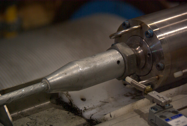
This is the Farmor connector through which all the load of the drill is
smoothly transferred to the cable. The circular piece to the
right of the
large nut rotates with the cable, and the rest of the drill does what
it wants.
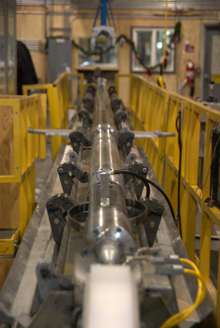
A view of the drill from the top.
A view of the "winch pit." The large motor on the left is the 150
hp "trip"
motor. It pulls and lowers the drill and cable at relatively
rapid rates.
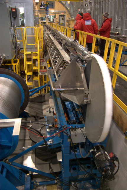
A view of the level wind assembly, and the top the tower,
when in the horizontal position. The motor in the lower
right runs the level wind via a long lead screw. The level
wind keeps the drill cable neatly wound on the winch.
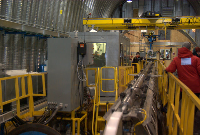
The winch control cabinet is on the left, with cables coming out of it
on the
bottom and back. The control room is in the center. The
control cabinet
houses drive controls for the large motors which run the winch.
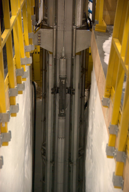
The drill being lowered into the bore hole. The tower
has been tilted vertical into the "slot", a narrow pit
approximately 30 feet deep and 5 feet wide that
provides the room for the tower to swing.
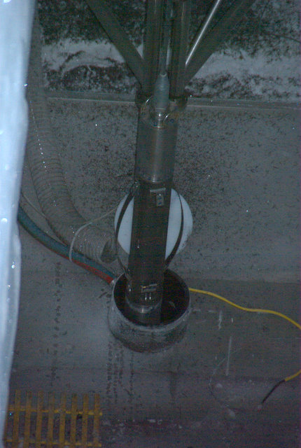
The top of the bore hole casing as the drill is being
lowered. There's tubes for drilling fluid, and drip
pans to funnel the drilling fluid back into the hole.
The white circle behind the drill is the bore hole cover
which is closed as soon as the drill is in the hole to
prevent something from accidentally dropping in the hole.
There's a slot in the cover to allow the cable to pass.
The yellow wire is a switch detector for the cover. This
picture was taken from some 40 or 50 feet away with a
flash as there's not good lighting at the bottom of the slot.
When the drill is at the bottom drilling, you can feel the vibrations
from the
cutting coming all the way up the cable. A multi-million dollar
version of two
tin cans and a string making a phone.
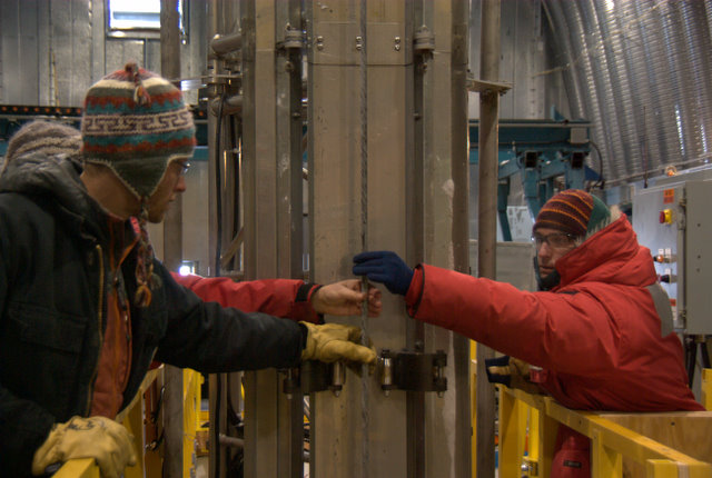
Here's an ice core at the surface, about to be removed. Drilling
fluid is
running out the end of the drill.
An ice core just delivered to the ice core handlers.
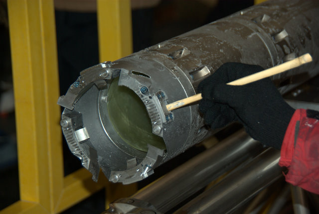
Using a piece of bamboo to clear ice chips from one of the core
dogs. If we
don't clean the ice from the drill head, a core dog could jam with ice
and
really chew up an ice core. Likewise, ice is cleared from the
cutter bits.